| AUTHOR | DATE CREATED | VERSION | DOCUMENT NUMBER |
|---|---|---|---|
| Dr. Peter Marshall | 9 February 2017 | V1.5 | CC11 – 00107 |
Introduction
This paper details investigations into the best glass to protect Ceramicx’s quartz cassette heaters allowing for best transmission of infrared radiation. A number of different glasses are available; however, these will have different characteristic transmission spectra due to differing compositions. By tuning the emission spectrum of the element to the transmission spectrum of the glass, the optimal combination for heating process energy efficiency can be identified.
Method
2.1 Materials
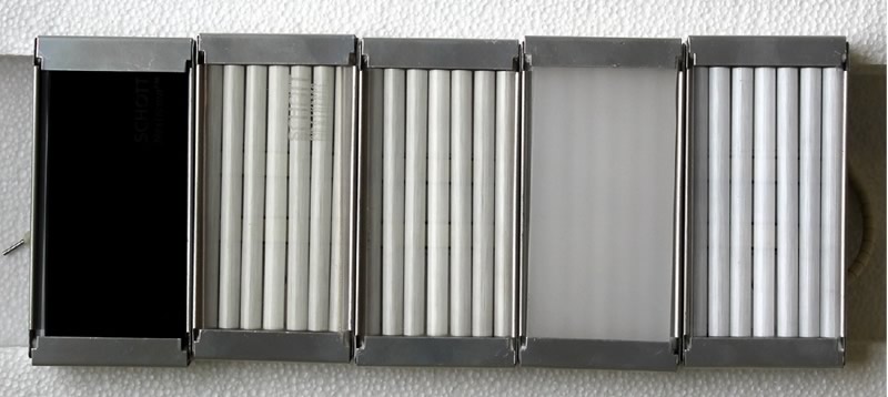
Five different quartz glasses were sourced, each with a thickness of 3mm. The first glass was Ceramicx standard protection Robax® glass. Two further glasses were obtained from Schott glass’s NextremaTM range (Materials 712-3 & 724-3). A further two glasses were sourced from another third party. These were transparent with a slight grey hue and a white, opaque colour or frosted appearance.
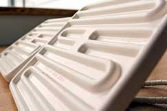
Each glass was mounted directly in front of a 500W, 230V HQE element (dimensions: 123.5 x 62.5mm). The heating coil was placed within 6 of the 7 available quartz glass tubes with the central tube left unheated. An image of each of the 5 glasses in-situ on the HQE heaters is shown in Figure 1
The data sheet for the three Schott glasses (NextremaTM 712-3, NextremaTM 724-3 & Robax®) shows the infrared transmission spectra which are shown in Figure 2. This shows the NextremaTM 712-3 transmits little or no radiation in the visible spectrum, consistent with the dark colour of the material, whereas far more radiation is transmitted by the NextremaTM 724-3 (Figure 2Error! Reference source not found.) and Robax® glasses. At longer wavelengths, the percentage radiation transmitted by the the NextremaTM 724-3 material is higher than the Robax® glass.
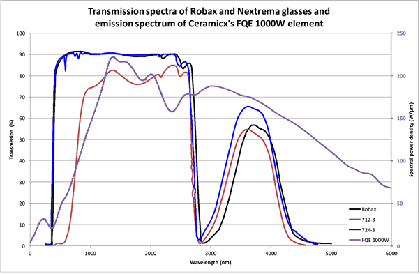
The HQE 500W heater has a peak spectral power density (emission) in the waveband of 2 – 4.2μm as shown in the spectrum (Error! Reference source not found.). Therefore, it would be expected that the glass with the greatest transmission in this region will exhibit the greatest heat flux in the experiment. This is particularly important at lower wavelengths which are more energetic than longer wavelengths.
2.2 Method
The heaters were mounted within the Herschel platform and energised. The voltage was adjusted such that the power output was 500 ± 1 W. The heater was allowed to heat up for a 10 minute period prior to testing commencing. Each heater was tested three times to increase accuracy.
2.3 Herschel
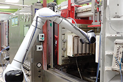
Ceramicx Herschel heat flux robot examines the total heat flux (W.cm-2) which is incident on the sensor. Heaters can be mounted in the Herschel and analysed using the 3D Infrared heat flux mapping routine. This automated system uses an infra-red sensor that is robotically guided around a pre-determined coordinate grid system in front of the heater emitter under test. The sensor has a maximum heat flux level of 2.3 W.cm-2 and measures IR in the band 0.4-10 micrometres. The coordinate system is a 500mm cubic grid in front of the heating emitter, see Figure 3. The robot moves the sensor in 25mm increments along a serpentine path in the X- and Z- directions, while the heating emitter is mounted on a slide carriage which increments in 100mm steps along the Y- direction.

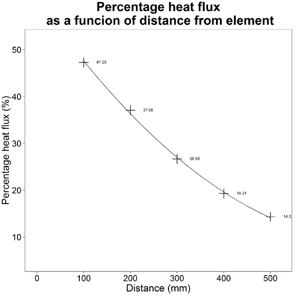
The results from the machine can be transformed into a percentage of total energy consumed returned as radiant heat flux from the heater. This decreases with increasing distance from the heater as the radiant heat flux diverges from the heater.
Results
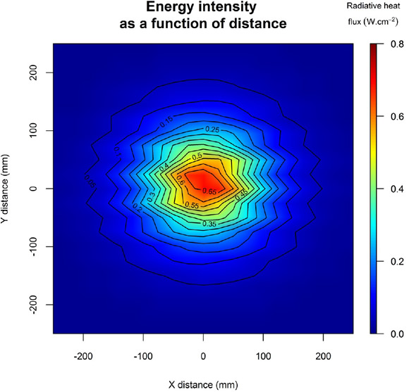
The results of the test show some interesting data which must be interpreted alongside the transmission and emission spectra of glass and Ceramicx’s HQE heating elements, respectively. All contour plots were made using the same colour scale to ensure visual comparison is possible.
3.1 NextremaTM 712-3
This dark tinted glass displays little or no radiation transmission in the visible spectrum (Figure 2); however, at longer wavelengths it is more transparent. The transmission drops off to <10% in the waveband of ≈ 2.8 – 3.2 μm, but recovers to ≥40% in the 3.5 – 4.2 μm band region.
The results show that, at 100mm, there is a peak power density of 0.6 W.cm-2, as shown in Figure 4. This shows that the peak heat flux, as expected, comes from the centre of the element and decreases concentrically with distance both from the centre of the element.
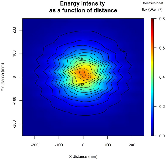
A similar plot can be produced for all distances from the heater; however, the general trend of decreasing heat flux from the element centre is the same.
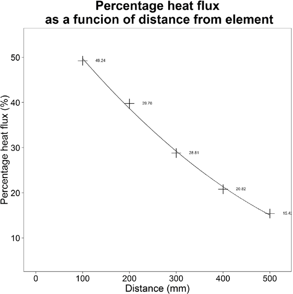
Similarly, the percentage radiative heat flux recorded decreases as the distance from the element increases (along the y-axis) as indicated in section 2.3. The magnitude of this decrease is shown in Figure 5
3.2 NextremaTM 724-3
The transparent NextremaTM glass (724-3) displays a slightly higher heat flux output than the 712-3 glass. This is primarily due to its better transparency (≈90%) in the more energetic visible and near-IR regions (0.5 < λ < 2.8 μm). When combined with the emission spectrum of the quartz element, a better match is seen which is confirmed by the higher heat flux recorded in the map (Figure 6)
The decrease in energy detected as a function of distance from the heater is very similar to that which is shown in Figure 5 for the same element with 712-3 protection glass.
3.3 Robax®
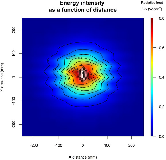
The Robax® glass shows a distinctly higher heat flux at the central point of the element which is off the general scale which was applied, as shown in Figure 7. In this case, the peak radiative heat flux is 0.80 W.cm-2. The higher heat flux at the centre is indicative of greater transmission due to higher source temperature (shorter IR wavelengths).
The reason for this slightly better performance is the increased IR transmission in the primary band (0.4<λ<2.8μm). For Robax® glass, the transmission drop occurs at a slightly longer wavelength which increases the output from the heater. The decreased and narrower bandwidth of transmission in the secondary band (3.2< λ<4.2μm) does not have the same influence as these wavelengths are not as energetic as the shorter wavelengths. The total heat flux recorded at 100 mm is, as expected, slightly higher than for the glasses examined in sections 3.1 and 3.2 due to the enhanced transmission properties of the glass. This is shown in Figure 8, below.
3.4 Frosted glass
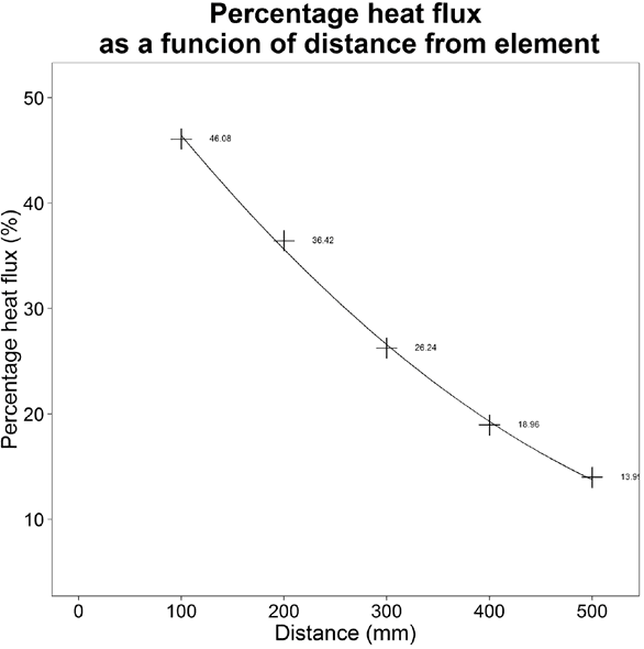
The heat flux map for the frosted glass protected heater is shown in Figure 9. This shows a similar pattern of energy emission from the heater to those detailed above. The detected heat flux magnitude is higher than those with NextremaTM protection but lower than that of the Robax® glass. As no transmission spectrum is available for this material, no insight can be given into the reasons behind this.
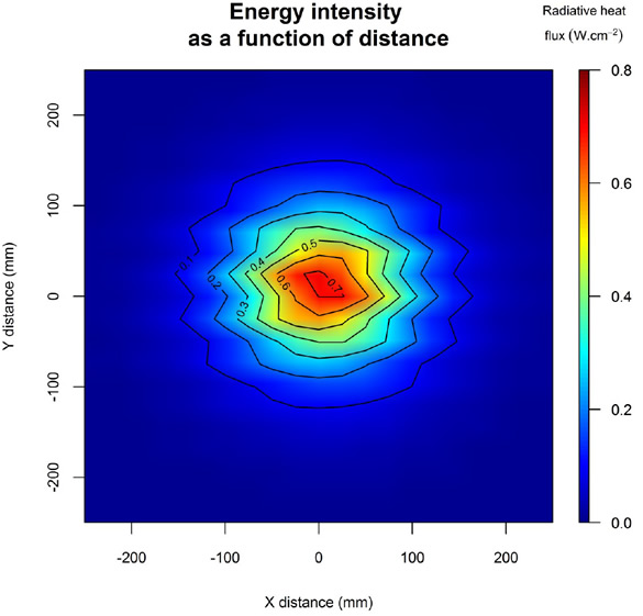
As the distance between the emitter and the heat flux sensor is increased, the detected heat flux falls off. The percentage heat flux detected at 100mm is lower than that of the Robax® glass which is shown in Figure 7, but higher than the NextremaTM glasses.
3.5 Transparent glass
The heat flux map for the transparent glass is shown in Figure 11. This shows very little discernible difference to the frosted glass material which was examined in section 3.4, indicative of very little change in the transmission spectrum of the glass in the active waveband region (2-4.2μm).
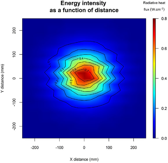
The total heat flux is slightly elevated compared to that of the frosted glass; however, it is still below that of the Robax® glass. Without transmission spectrum data, no explanation can be offered for this observation.
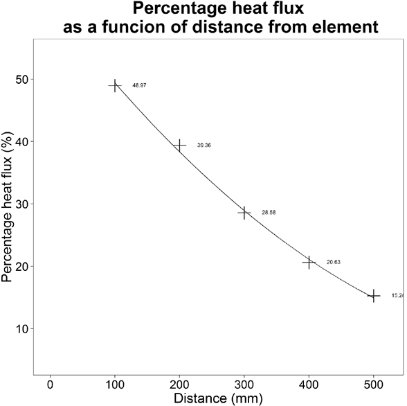
Table 1 shows the average maximum heat flux which was recorded for the element across the three conducted tests as well as the average percentage heat flux recorded at 100 and 200mm from the element surface. This indicates that the two NextremaTM and the Frosted glasses performed poorly, however, there is little to separate the Robax® and the Transparent glasses.

A measurement phenomenon occurs during heat flux mapping whereby the initial reading taken is a reference value, designated zero and each recorded value is measured relative to this. At short separations, the heat flux can, therefore, be recorded as negative which gives rise to the uncoloured regions in the contour plots.
Normalising the raw data reveals that the Robax® and Transparent glasses are indeed the most efficient glass for transmitting the radiation as shown in Table 2.

Given no spectral data is available for the Transparent glass, it is not possible to give a definitive reason as to why the difference between this and Robax® occurs and whether it is the transparency level in the visible/near-IR (0.5 – 2.8μm) or in the medium wave region (≥3 μm).
It is noticeable that the maximum heat flux recorded for Robax® is higher than for the Transparent glass. This may be indicative of a change in the infrared transparency as a function of temperature, with Robax® becoming more transparent at the elevated temperatures seen in the central portion of the element.
Conclusion
The results of the experiment above show that the Robax® glass, currently used by Ceramicx, to protect its heaters possesses one of the best IR transmission properties for the quartz cassette heaters. This is because the transmission spectrum for this glass is at a maximum in the active waveband of the heater.
For optimal heating, the transmission spectrum of the protection glass should be matched to the emission spectrum of the heater that it is protecting. In this case, the glass should be as transparent as possible in the 1 – 3.2 μm waveband.
It should be noted that the power density of the element and a variety of other factors will influence the results of this experiment. Should the power per unit area of the element change, the results will change. Moreover the results indicated in this experiment are not representative of a platen type configuration.
1 A 1000W FQE and 500W HQE have the same power density and therefore similar emission characteristics
Disclaimer
These test results should be carefully considered prior to a determination on which type of infrared emitter to use in a process. Repeated tests conducted by other companies may not achieve the same findings. There is a possibility of error in achieving the set-up conditions and variables that may alter the results include: the brand of emitter employed, the efficiency of the emitter, the power supplied, the distance from the tested material to the emitter utilised and the environment. The locations at where the temperatures are measured may also differ and therefore affect the results.


